
AQUA

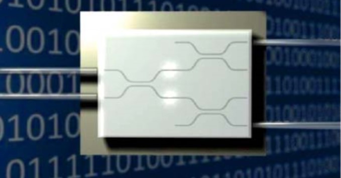
The AQUA laboratory is devoted to the characterization of integrated photonic circuits conceived for advanced quantum applications. The progress of quantum technologies promises remarkable advantages in terms of computational capabilities and secure communications, in addition to other improvements in the fields of sensors and imaging. The advance of quantum optics is strictly related to the development of integrated photonic circuits, that can bring evident advantages in terms of compactness and stability if compared to bulk optics. The integrated circuits that are studied in this laboratory are fabricated by the femtosecond laser writing technology in transparent substrates. This fabrication technique provides photonic circuits of high quality, allowing the manipulation of polarization encoded qubits.
This laboratory is equipped with an instrumentation suitable for the characterization of integrated photonic circuits.
Measurement of the refrative index profile
A preliminary characterization consists in the measurement of the refractive index profile, that can be directly measured with a refractive index profilometer (Rinck Electronic 2D). By means of the refracted near-field technique, the profilometer can measure the refractive index contrast with a precision of 10-4 and a spatial resolution of 0.5 µm.
Laser sources
The complete characterization of the device includes the propagation losses measurement and the analysis of the guided mode profile for estimating the coupling losses. In this laboratory there are lasers with different wavelengths: He-Ne lasers (633 and 543 nm), many semiconductor lasers in the near infrared (wavelengths from 700 nm to 1550 nm) and one at 405 nm.
Instrumentation for the characterization of optical circuits
For studying the properties of the developed circuits, the light emitted by these sources should be coupled with their input waveguides. For this purpose, in the laboratory there are many optical fibers (for the “butt-coupling”) and objectives for focusing the laser beam on the input facet of the device (“end-fire” coupling). The relative positioning between the optical chip and the fiber or the input laser beam is provided by translators with a submicrometric precision, manual or motorized and controlled by a computer. An optical microscope can be used to control the alignment between the optical fiber and the sample.
It is possible to characterize the birefringence of the optical waveguides by means of polarizers and birefringent half and quarter-wave plates. These optical components are mounted on motorized rotators for a semi-automatic measurement.
Finally, in the laboratory there are some power supplies for controlling some active components of the characterized devices. For example, some thermal phase shifters made of gold can be deposited on top of the optical waveguides: being heated by Joule effect by a flowing current, they can change the propagation constant of the waveguide they are acting on, thus inducing a phase difference between two or more waveguides.